1. Introduction
1.1. Motivation
The City Geography Markup Language (CityGML) is an international OGC standard for the representation and exchange of virtual 3D city and landscape models.
LoD 1 and LoD 2 models of buildings are available for a large number of cities and countries.
Data gathering methods such as Mobile Mapping Systems and emerging applications such as urban digital twins begin to shift this focus towards models of road infrastructure.
Several cities (such as New York City, Melbourne, Munich or Singapore) have detailed data on roads and the streetspace available (usually within an ArcGIS or QGIS environment). However, this data is often structured in different ways (semantically and geometrically). Modelling this data within a common representation framework allows the immediate usage of the data with the same tools for a number of applications.
While standards such as GDF or OpenDRIVE focus on linear (graph-based) or parametric representations of roads, CityGML 3.0 allows linear, polygonal as well as volumetric (explicit) geometries integrated within a consistent semantic 3D city model including models of buildings, vegetation, city furniture, tunnels or bridges.
CityGML version 3.0 provides revised and extended concepts for modelling roads and the streetspace presented and explained in this documentation.
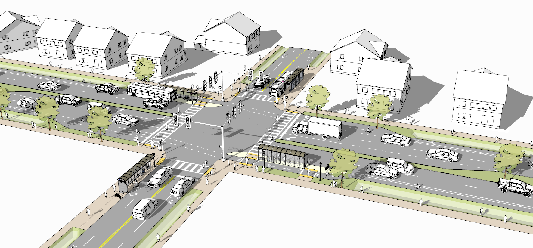
Figure 1 Digital 3D streetspace model including road infrastructure, city furniture, vegetation and buildings (own illustration based on SketchUp model).
1.2. Scope
This document provides recommendations for modelling road infrastructure in the context of semantic 3D city models.
Recommendations are related to the conceptual model of the Open Geospatial Consortium (OGC) standard CityGML version 3.0.
The CityGML Transportation module defines central elements of the traffic infrastructure. This includes the transportation objects Road, Track, Railway, Waterway and Square.
Concepts presented in this document apply to all of these transportation types (and their interactions, e.g. a level crossing of Road and Railway infrastructure).
The focus of this document is on models of Roads and their parts (including individual driving lanes, pedestrian sidewalks, bike lanes, etc.).
The CityGML conceptual model allows various geometrical representations for objects such as transportation infrastructure (e.g. linear, volumetric or point clouds). The modelling examples given in this document focus on surface-based polygonal representations using explicit geo-referenced geometries.
Data and modelling examples in this document are based on the GML encoding of CityGML.
Most example datasets presented in section 4 are provided as Open Data.
In addition to modelling concepts, this document provides (some) data recording recommendations. However, this is not a data recording manual.
This document can be seen as an addition and extension to the CityGML User Guide with a specific focus on modelling roads.
1.3. Target group
Municipalities, companies, data providers, mapping agencies and other stakeholders interested in creating and using urban digital twins of road infrastructure and the streetspace in the context of semantic 3D city models. This can include applications such as urban planning and management, automotive applications, environmental simulations and analyses or topographic mapping.
1.4. References
The conceptual model of CityGML version 3.0 as well as relevant publications in the context of semantic road modelling using CityGML are listed in this section.
- Kolbe2021
Kolbe, T.H., Kutzner, T., Smyth, C. S., Nagel, C., Roensdorf, C., Heazel, C. (2021), OGC City Geography Markup Language (CityGML) Part 1: Conceptual Model Standard, OGC Document 20-010, https://docs.ogc.org/is/20-010/20-010.html
- Beil2020a
Beil, C., Ruhdorfer, R. Coduro, T., Kolbe, T. H. (2020), Detailed Streetspace Modelling for Multiple Applications: Discussions on the Proposed CityGML 3.0 Transportation Model, ISPRS International Journal of Geo-Information, 9(10), 603, https://doi.org/10.3390/ijgi9100603
- Beil2020b
Beil, C., & Kolbe, T. H. (2020), Combined modelling of multiple transportation infrastructure within 3D city models and its implementation in CityGML 3.0, Int. Arch. Photogramm. Remote Sens. Spat. Inf. Sci, VI-4/W1, 29-36, https://doi.org/10.5194/isprs-annals-VI-4-W1-2020-29-2020
- Kutzner2020
Kutzner, T., Chaturvedi, K., Kolbe, T. H. (2020), CityGML 3.0: New functions open up new applications. PFG–Journal of Photogrammetry, Remote Sensing and Geoinformation Science, 88(1), 43-61, https://doi.org/10.1007/s41064-020-00095-z
- Schwab2020
Schwab, B., Beil, C., Kolbe, T. H. (2020) Spatio-semantic road space modeling for vehicle–pedestrian simulation to test automated driving systems. Sustainability, 12(9), 3799, https://doi.org/10.3390/su12093799
- Boersma2019
Boersma, F., (2019), Modelling different levels of detail of roads and intersections in 3D city model, Master’s Thesis, Delft University of Technology, http://resolver.tudelft.nl/uuid:ebfc48f8-4704-47d3-9654-cd00c765e0af
- Tamminga2019
Tamminga, G. (2019), A Novel Design of the Transport Infrastructure for Traffic Simulation Models, PhD Thesis, Delft University of Technology, https://doi.org/10.4233/uuid:35d2e152-0cfe-439e-a276-da4a69b11acd
- Labetski2018
Labetski, A., van Gerwen, S., Tamminga, G., Ledoux, H., Stoter, J. (2018), A proposal for an improved transportation model in CityGML, Int. Arch. Photogramm. Remote Sens. Spat. Inf. Sci, XLII-4/W10, 89–96, https://doi.org/10.5194/isprs-archives-XLII-4-W10-89-2018
- Beil2017
Beil, C., & Kolbe, T. H. (2017), CityGML and the streets of New York - A proposal for detailed street space modelling, Int. Arch. Photogramm. Remote Sens. Spat. Inf. Sci, IV-4/W5, 9-16, https://doi.org/10.5194/isprs-annals-IV-4-W5-9-2017
1.5. Data downloads
Hint
Most example datasets presented in section 4 can be downloaded from this repository.
This includes basic as well as real-world examples.
Hint
The open-source converter r:trån reads road network models in the OpenDRIVE data format and transforms them to the virtual 3D city model standard CityGML (versions 2.0 and 3.0).
Find more information on this converter on the corresponding GitHub page.
1.6. Licence and disclaimer
Note
This guideline is licenced under the Creative Commons Attribution 4.0 International (CC BY 4.0) licence.
The provided datasets are free for usage.
No warranties or guarantee on the correctness, completeness, or appropriateness of the provided datasets for any specific use is given.
In no case can the data providers be held liable for damages, caused directly or indirectly, by using or working with these datasets or software tools.
Since the data provided here has been derived from Open Data, all original terms of use and conditions apply here too.
Aerial imagery included in this document is derived from Open Data sources.
Some of the conceptual illustrations in this document were created based on 3D models available in the SketchUp Warehouse.
2. General concepts and definitions
General concepts and definitions of the CityGML 3.0 conceptual model, important in the context of modelling roads are summarized in this section. For more detailed explanations on these general concepts please refer to the CityGML 3.0 standard document.
2.1. The CityGML 3.0 Transportation module
The CityGML Conceptual Model uses a modularized structure and provides models for the most important types of objects within virtual 3D city and landscape models.
This includes a Transportation module for roads and other transportation infrastructure.
The UML diagram of the CityGML 3.0 Transportation module is shown in Figure 2.
For other relevant modules such as the Core module please refer to the CityGML standard document.
Real-world objects are represented by geographic features according to the definition in ISO 19109.
Geographic features of the same type (e.g. Roads) are modelled by corresponding feature types that are represented as classes in the Conceptual Model.
Following a hierarchical structure, the specific feature types like Roads are defined as subclasses of more general higher-level classes.
Roads, Railways, Tracks and Waterways can be segmented into individual Sections and Intersections, which can be further segmented into individual (Auxiliary)TrafficSpaces, which again can be bounded towards the ground by (Auxiliary)TrafficAreas.
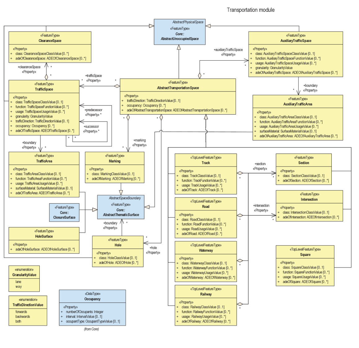
Figure 2 UML diagram of the CityGML 3.0 Transportation module.
2.2. Semantic concepts
2.2.1. Modelling spaces and space boundaries
In the CityGML 3.0 Conceptual Model, a clear semantic distinction of spatial features is introduced by mapping all city objects onto the semantic concepts of spaces and space boundaries.
Definitions
A space is an entity of volumetric extent in the real world. Buildings, Waterbodies, Vegetation, Rooms, and TrafficSpaces are examples for such entities with volumetric extent.
A space boundary is an entity with areal extent in the real world. Space boundaries delimit and connect spaces.
FeatureTypes such as Road, Railway, Track, Waterway or Square are subclasses of the abstract class AbstractTransportationSpace.
Transportation objects are not just represented by their surface but also consider the space above used for transportation.
Concepts of (Auxiliary)TrafficSpaces bounded by corresponding (Auxiliary)TrafficAreas are explained in more detail in the respective chapters of this document.
2.2.2. Three levels of granularity
For defining different levels of semantic decomposition for transportation objects, three levels of granularity are introduced.
Definitions
In granularity ‘area’ the entire width of a Road is modelled with one single object. This corresponds to the extent of a Section or Intersection.
In granularity ‘way’ individual objects are modelled per surface function (or traffic type). This means one object per carriageway is used. Sidewalks, bicycle paths, pedestrian crossings, parking bays, etc. can be modelled as individual objects.
In granularity ‘lane’ each individual lane (including driving lanes for vehicles) are modelled separately.
These three levels of granularity can be modelled geometrically using linear or polygonal representations (corresponding volumetric representations can be created by extruding the polygonal surface representation).
Examples for these three levels of granularity for polygonal (surface-based) representations are given in Figure 3.
For the linear representations one centerline is used to model the entire Road. In granularity ‘way’ individual lines are used for carriageways and pedestrian or bicycle paths. In granularity ‘lane’ each driving lane is modelled with an individual linear representation.
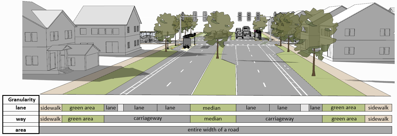
Figure 3 Three levels of granularity for polygonal representations of Roads (own illustration based on SketchUp model).
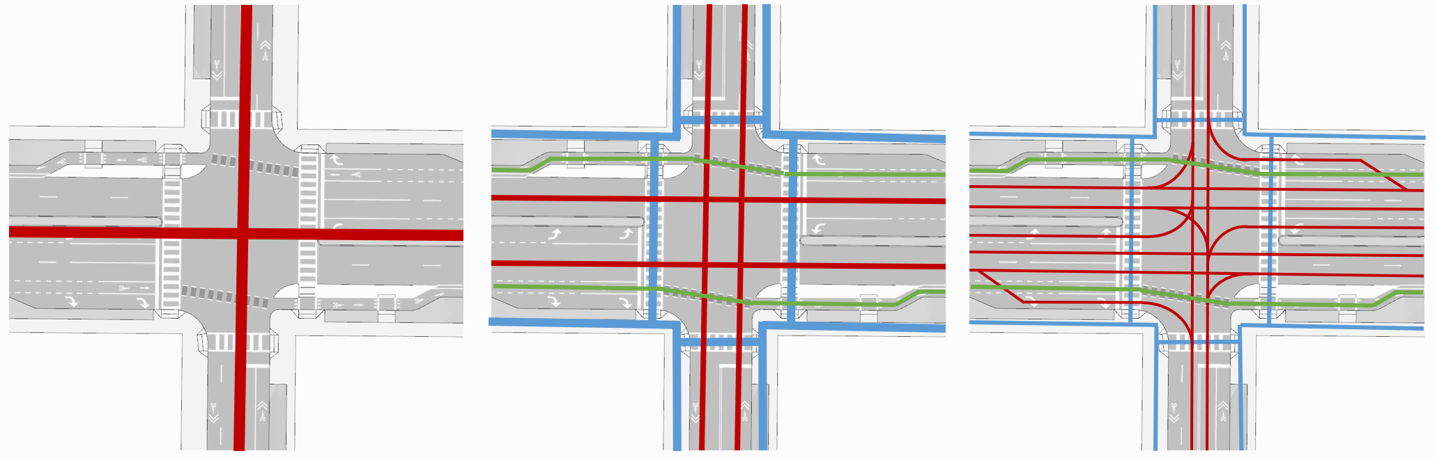
Figure 4 Three levels of granularity (area, way and lane) for linear representations of Roads (red = driving, blue = pedestrian, green = bicycle) (own illustration based on SketchUp model).
2.2.3. Required and recommended attributes
Required
In order to distinguish and reference individual objects, each object has to have a unique identifier (gml:id).
(Auxiliary)TrafficSpaces require a granularity attribute (way or lane).
Recommended
Road objects should contain an individual gml:name attribute.
Sections and Intersections should contain information to which Road(s) they belong. This can be achieved by corresponding gml:name attribute(s).
TrafficSpaces should contain information which Section or Intersection they belong to. This is implicitly given due to the hierarchal file structure of a GML encoded CityGML document.
(Auxiliary)TrafficAreas should contain a function attribute indicating their type (e.g. driving lane, sidewalk, parking lane, bike lane, etc.)
(Auxiliary)TrafficAreas can contain a surface material attribute.
2.2.4. Codelists
Codelists for the CityGML 2.0 Transportation module as defined by the Special Interest Group 3D (SIG3D) are available here. This includes codelists for (Auxiliary)TrafficAreas and TransportationComplex objects (e.g. Roads). These can be transferred and applied to respective CityGML 3.0 classes.
The following tables provide recommendations for AuxiliaryTrafficAreas and TrafficAreas that should be explicitly modelled by providing respective usage and function attributes. Multiple usage and function attributes can be modelled per AuxiliaryTrafficAreas and TrafficAreas. Function describes surface types such as driving lane, footpath, or cycle lane, while the usage attribute indicates which modes of transportation can use it (e.g. pedestrian, car, tram).
citygml_usage (text) |
citygml_usage (code) |
|---|---|
pedestrian |
1 |
car |
2 |
truck |
3 |
bus, taxi |
4 |
train |
5 |
bicycle |
6 |
motorcycle |
7 |
tram |
8 |
emergency |
15 |
citygml_function (text) |
citygml_function (code) |
|---|---|
driving_lane |
1 |
footpath |
2 |
cyclepath |
3 |
combined foot-/cyclepath |
4 |
square |
5 |
parking_lay_by |
7 |
rail |
8 |
rail_road_combined |
9 |
crosswalk |
20 |
bus_lay_by |
32 |
motorway |
33 |
emergency_lane |
36 |
road_works |
37 |
unknown |
9999 |
citygml_function (text) |
citygml_function (code) |
|---|---|
shoulder |
1010 |
green_area |
1020 |
kerbstone |
1220 |
restricted |
1240 |
traffic_island |
1300 |
raised_median |
1400 |
low kerbstone |
1500 |
border |
1600 |
road_channel |
1700 |
The attribute surfaceMaterial specifies the type of pavement and can be used by AuxiliaryTrafficAreas and TrafficAreas.
citygml_surfaceMaterial (text) |
citygml_surfaceMaterial (code) |
|---|---|
asphalt |
1 |
concrete |
2 |
pavement |
3 |
cobblestone |
4 |
gravel |
5 |
soil |
8 |
sand |
9 |
grass |
10 |
2.2.5. Generic attributes
While CityGML provides some standardized attributes such as function, usage or surface material, it is possible to create and use generic attributes.
(Auxiliary)TrafficAreas should contain information on individual surface areas (e.g. in square meter) as generic attributes.
Depending on intended applications additional generic attributes are possible (e.g. pavement rating, maximum speed, number of lanes, etc.).
2.3. Geometric representations
Spatial properties of all CityGML feature types are represented using the geometry classes defined in ISO 19107.
Spatial representations can have 0-, 1-, 2-, or 3-dimensional extents depending on the respective feature type and Levels of Detail.
CityGML makes use of different kinds of aggregations of geometries like spatial aggregates (MultiPoint, MultiCurve, MultiSurface, MultiSolid) and composites (CompositeCurve, CompositeSurface, CompositeSolid).
Volumetric shapes are represented in ISO 19107 according to the so-called Boundary Representation (B-Rep).
CityGML 3.0 supports point cloud geometries. Point clouds can either be provided inline within a CityGML file or as reference to external point cloud files of common file types such as LAS or LAZ.
Recommendations for modelling Roads using polygonal (surface-based) representations are given in this document.
For more general recommendations on using geometries in CityGML, please refer to this guideline
2.3.1. Coordinate Reference Systems
Nearly all geometries in CityGML use 3D coordinates.
Single points and also the points defining the boundaries of surfaces and solids have three coordinate values (x,y,z) each.
Coordinates always have to be given with respect to a Coordinate Reference System (CRS) that relates them unambiguously with a specific position on the Earth.
In contrast to CAD or BIM, each 3D point is absolutely georeferenced, which makes CityGML especially suitable to represent geographically large extended structures like roads, where the Earth curvature has a significant effect on the object’s geometry.
In most CRS, the (x,y) coordinates refer to the horizontal position of a point on the Earth’s surface. The z coordinate typically refers to the vertical height over (or under) the reference surface.
Note that depending on the chosen CRS, x and y may be given as angular values like latitude and longitude or as distance values in meters or feet.
According to ISO 19111, numerous 3D CRS can be used. This includes global as well as national reference systems using geocentric, geodetic, or projected coordinate systems.
2.3.2. Levels of Detail (LoD)
The CityGML Conceptual Model differentiates four consecutive Levels of Detail (LOD 0-3).
CityGML datasets can (but do not have to) contain multiple geometries for each object in different LODs simultaneously.
Levels of Detail are no longer associated with the degree of semantic decomposition of city objects and refer to the spatial representations only.
In order to maintain the ability for a semantic decomposition of transportation objects, three levels of granularity are introduced.
2.3.3. Adaption to the terrain
Data on road infrastructure are often provided as 2D data with a base height of 0 meter.
For adapting this data to the terrain it is recommended to create a terrain with breaklines of individual (Auxiliary)TrafficAreas.
Triangles of this new terrain, that are part of individual (Auxiliary)TrafficAreas, can then be used to represent the geometry of those surfaces.
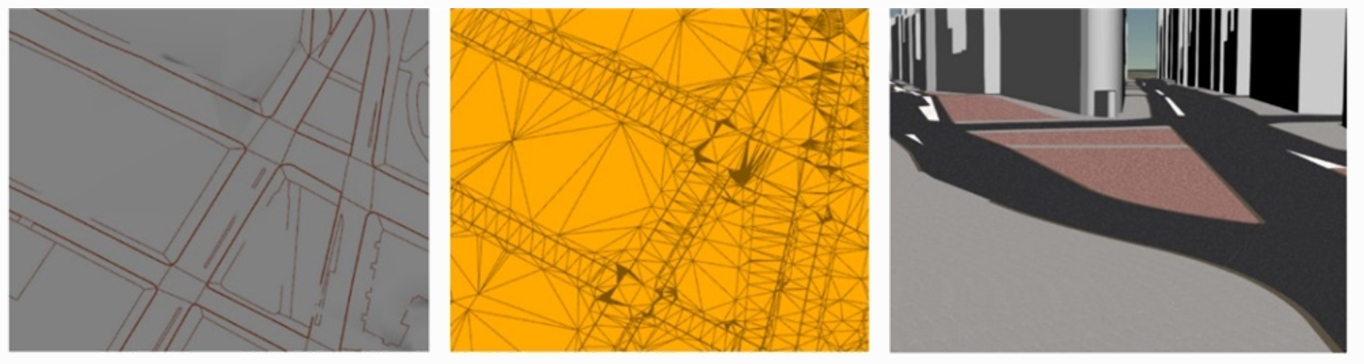
Figure 5 Adaption of road surfaces (TrafficAreas) to the terrain using breaklines and triangulations.
2.3.4. Subtle 3D structures such as raised medians
In addition to the adaption of road surfaces to the terrain, subtle geometric features such as kerbstones or traffic islands can be modelled.
It is recommended to derive these structures from 2D data by extruding respective (Auxiliary)TrafficAreas by a certain amount (e.g. 0.15m).
MultiSurface geometries are recommended for these objects.
It is possible to use volumetric Solid geometries for representing subtle structures such as kerbstones or traffic islands. In this case, the surfaces of these Solids correspond to TrafficAreas as they bound the respective object towards the ground. The volumetric space above these objects, however, should be modelled as (Auxiliary)TrafficSpaces.
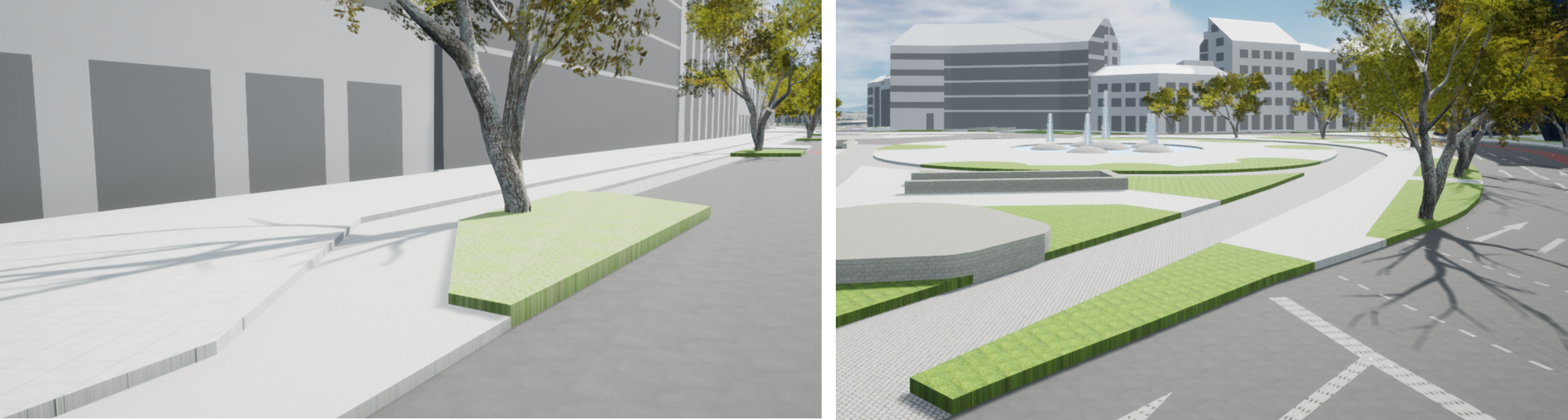
Figure 6 Modelling raised sidewalks, kerbstones or medians.
2.4. Topological concepts
2.4.1. Predecessor / Successor relations
TrafficSpaces can contain information about respective predecessors and successors using the XLink concept.
This is especially recommended for linear representations of TrafficSpaces in granularity ‘lane’ (e.g. to support routing applications).
However, this is also available for other geometric representations and granularities of TrafficSpaces.
2.4.2. XLinks
XLinks are an XML specific concept for representing topology.
Each geometry object that should be shared by different geometric aggregates or different thematic features is assigned an unique identifier, which may be referenced by a GML geometry property using a href attribute.
Intersections for example can be linked to multiples Roads simultaneously.
This allows a non-redundant geometrical representation of Intersections, while indicating their affiliation with multiple Roads.
Advantage: Semantically and geometrically identical objects do not need to be represented multiple times.
Disadvantage: In large files, linked objects may be stored very far apart.
2.4.3. CityObjectRelations
Using CityObjectRelations makes sense for linking semantically different but geometrically identical surfaces / objects.
CityObjectRelations are realised using XLinks, indicating relations and their type between objects.
Advantage: Geometry of each object is stored directly with the object. Information on identical (geometrically equal) surfaces is available.
Disadvantage: Geometry of objects / surfaces needs to be represented redundantly.
2.5. Appearance
The CityGML Appearance module provides the representation of surface data such as observable properties for surface geometry objects in the form of textures and material.
For Road surfaces this may be corresponding colors, synthetic textures (e.g. asphalt) or aerial images (e.g. a high resolution digital orthophoto).
Appearances are not limited to visual data but represent arbitrary categories called themes (such as solar irradiation for urban heat islands, infrared radiation or noise pollution).
For the visualization of road infrastructure, it might be necessary to offset road surface geometries slightly above the ground in order to avoid rendering problems (z-fighting) with underlying models of the terrain.
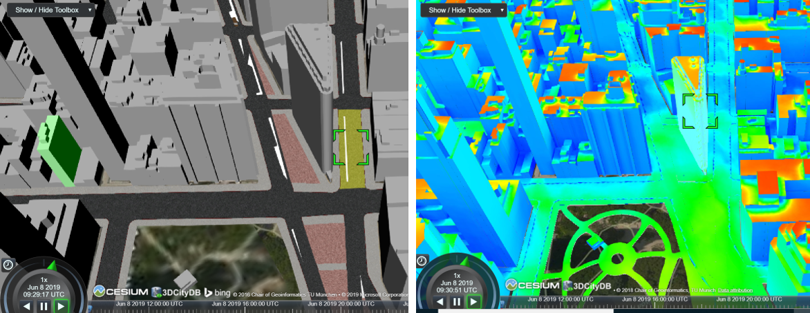
Figure 7 Different appearances for road surfaces. Synthetic textures (left). Results of a solar irradiation simulation (right).
3. Modelling Roads according to concepts of CityGML 3.0
The following modelling examples are illustrated using semantic 3D city and streetspace models from different cities such as Melbourne, New York, Munich or Ingolstadt.
3.1. Roads
Transportation objects such as Roads, Tracks, or Railways are defined as specific subclasses of the abstract class AbstractTransportationSpace.
Definition
A Road is a transportation space used by vehicles, bicycles and/or pedestrians.
Each Road
must contain a unique gml:id attribute.
should be distinguished by individual names stored as a gml:name attribute.
should cover the entire width of corresponding transportation infrastructure including sidewalks, bicycle lanes, etc., adjacent to carriageways.
should consist of individual Sections and Intersections.
can contain multiple function and usage attributes.
can contain a class attribute.
In case multiple (disconnected) roads within one city model have the same name, individual Road objects per road should be created.
In case a Road does not have a name, logical aggregations of underlying Sections and Intersections should be performed.
Multiple Roads can share the same Intersection.
Long uninterrupted Roads (e.g. freeways or motorways) can be segmented into multiple Sections directly connected to each other (without intermediate Intersections).
Figure 8 shows three Road objects highlighted in purple, yellow and green. Note that these Roads have shared Intersections
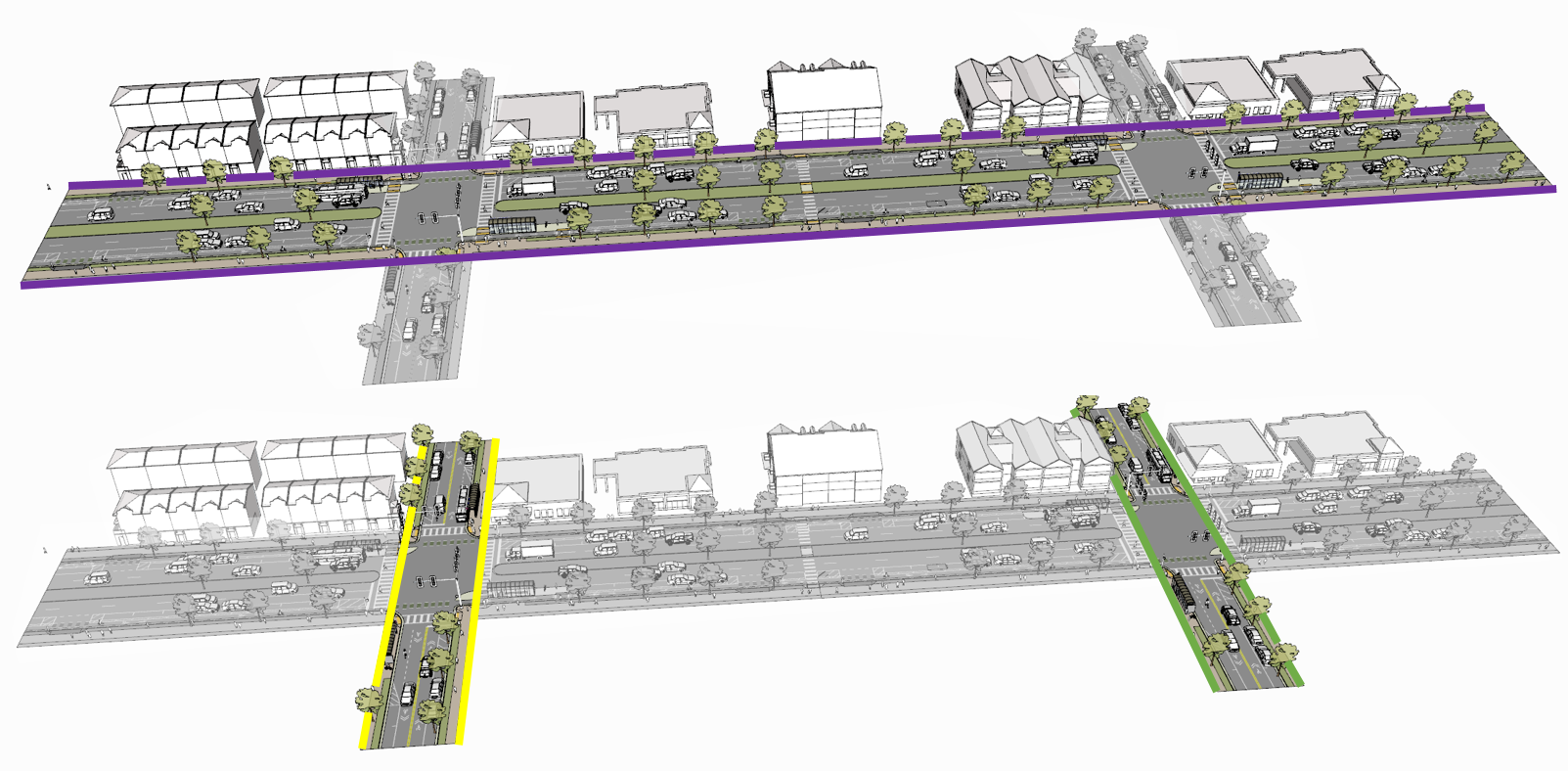
Figure 8 Three Road objects highlighted in purple, yellow and green with shared Intersections (own illustration based on SketchUp model).
3.2. Sections and Intersections
Roads (or Tracks, Railways, Waterways) should be decomposed into individual Sections and Intersections.
Sections and Intersections
must contain a unique gml:id attribute.
should cover the entire width of a Road and thus directly correspond to the representation of transportation objects in granularity ‘area’.
can contain a class attribute.
do not need to alternate. In some cases it might be useful to have individual Sections directly next to each other.
3.2.1. Sections
Definition
A Section is a transportation segment that can clearly be assigned to one Road (or Railway, Track, Waterway) object.
Each Section
should indicate its type (e.g. road corridor, dead end, etc.) by a corresponding class attribute.
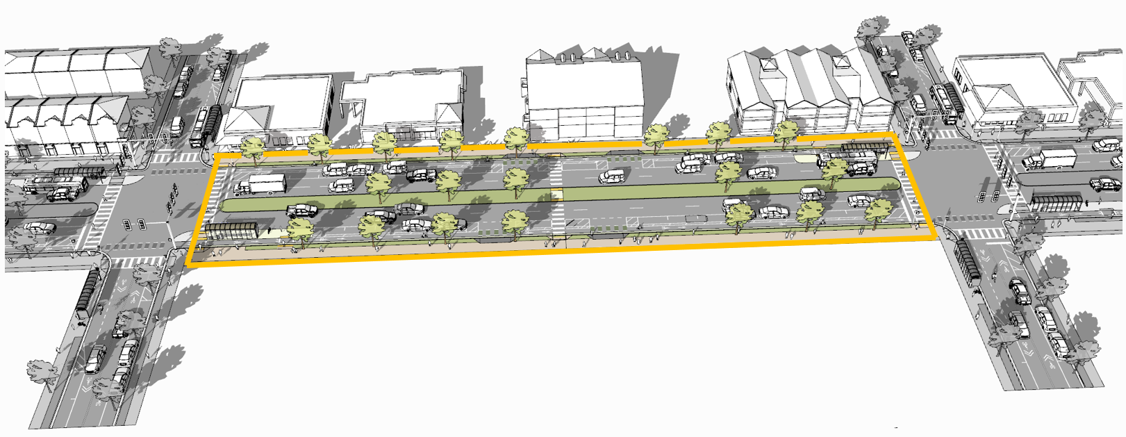
Figure 9 Typical example of a Section (surrounded with orange lines) between two intersections (own illustration based on SketchUp model).
3.2.2. Intersections
Definition
An Intersection is a transportation space that is a shared segment of multiple Roads or other transportation objects such as Railways (e.g. a crossing of two Roads or a level crossing of a Road and a Railway).
Each Intersection
should indicate affiliations to multiple Roads with multiple gml:name attributes (one for each Road they belong to).
should indicate its type (e.g. Y-Intersection, T-Intersection, 4-way Intersection, roundabout, etc.) using a corresponding class attribute.
can be shared by multiple Roads using mentioned XLink concept.
Depending on intended use-cases, different definitions of the extent of individual Intersections are possible.
It is recommended to model Intersections with the minimal extent of surfaces shared by multiple Roads. However, it is not prohibited to expand Intersection objects into adjacent Sections.
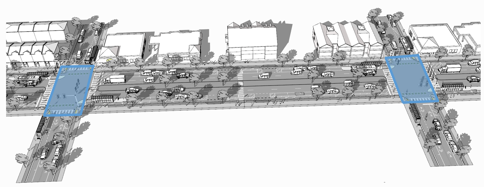
Figure 10 Two Intersections (highlighted in blue) (own illustration based on SketchUp model).
3.3. TrafficSpaces and AuxiliaryTrafficSpaces
Transportation objects are not just represented by their surface but also consider the space above used for transportation.
Sections and Intersections should consist of multiple AuxiliaryTrafficSpaces and TrafficSpaces.
(Auxiliary)TrafficSpace represent the (typically free) space above corresponding (Auxiliary)TrafficAreas.
Definitions
A TrafficSpace is a space in which traffic takes place. Traffic includes the movement of entities such as cars, trains, vehicles, pedestrians, ships, or other transportation types.
An AuxiliaryTrafficSpace is a space within the transportation space not intended for traffic purposes.
Each (Auxiliary)TrafficSpace
must contain a unique gml:id attribute.
must contain a granularity attribute (‘way’ or ‘lane’).
should contain a function attribute indicating the type of (Auxiliary)TrafficSpaces.
can contain a class attribute.
can contain multiple function attributes.
can contain multiple usage attributes indicating which types of traffic members use certain spaces.
Each TrafficSpace additionally
can contain a traffic direction attribute (forwards, backwards or both).
can contain an occupancy attribute (e.g. to indicate the number of pedestrians using a particular TrafficSpace at a certain time).
can have an optional ClearanceSpace.
Multiple TrafficSpaces can be linked using the predecessor / successor concept.
Volumetric or linear representations are recommended for modelling individual (Auxiliary)TrafficSpaces. Point cloud geometries are also possible.
Volumetric representations of (Auxiliary)TrafficSpaces can be generated by extruding corresponding (Auxiliary)TrafficAreas by a certain amount.
In Germany, for example, car driving lanes typically have a free space height of 4.5 m and sidewalks of 2.5 m. This can be modelled using volumetric geometries.
(Auxiliary)TrafficSpaces do not have to be represented geometrically but should be bounded towards the ground by corresponding (Auxiliary)TrafficAreas.
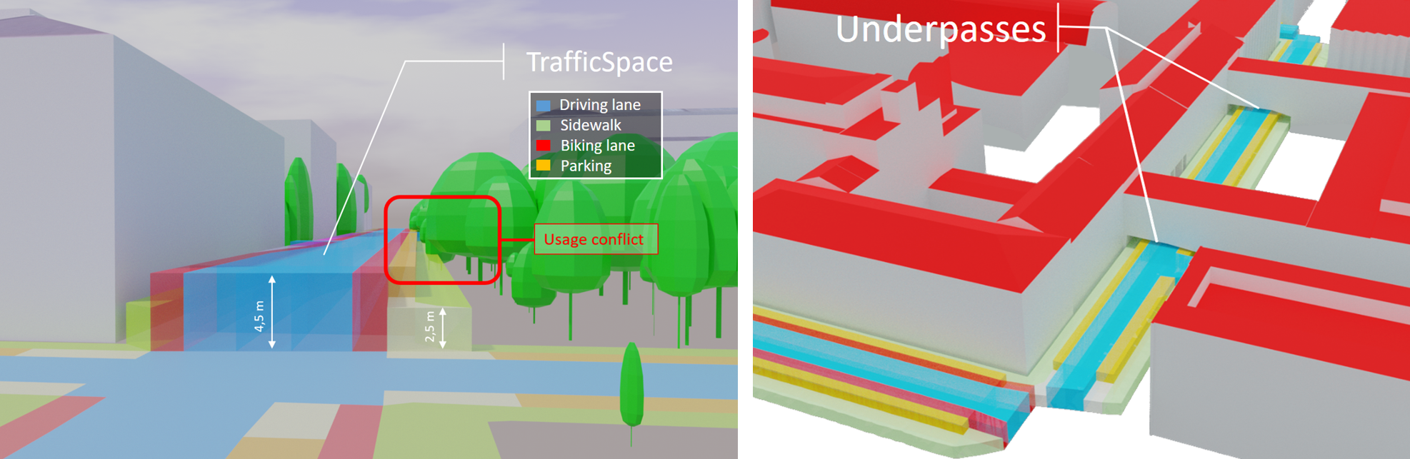
Figure 11 Volumetric representations of TrafficSpaces with different heights according to respective functions (left), TrafficSpaces underneath Building underpasses (right).
3.4. TrafficAreas and AuxiliaryTrafficAreas
Definitions
A TrafficArea is the ground surface of a TrafficSpace. TrafficAreas are the surfaces upon which traffic actually takes place, such as car driving lanes, pedestrian sidewalks or bicycle lanes.
An AuxiliaryTrafficArea is the ground surface of an AuxiliaryTrafficSpace. AuxiliaryTrafficAreas are describing further elements of the Road, like kerbstones, raised medians, and green areas not intended for direct traffic usage.
Each (Auxiliary)TrafficArea
must contain a unique gml:id attribute.
should contain a function attribute indicating the type of (Auxiliary)TrafficAreas (e.g. driving lane, sidewalk, median, etc.).
can contain a class attribute.
can contain multiple function attributes. A pedestrian crossing for example can contain a function ‘driving lane’ as well as a function ‘footpath’.
can contain multiple usage attributes indicating which types of traffic members use certain surfaces (e.g. cars, pedestrians or bicyclists).
should not have overlapping geometries but rather be represented with separate (Auxiliary)TrafficAreas with multiple function attributes.
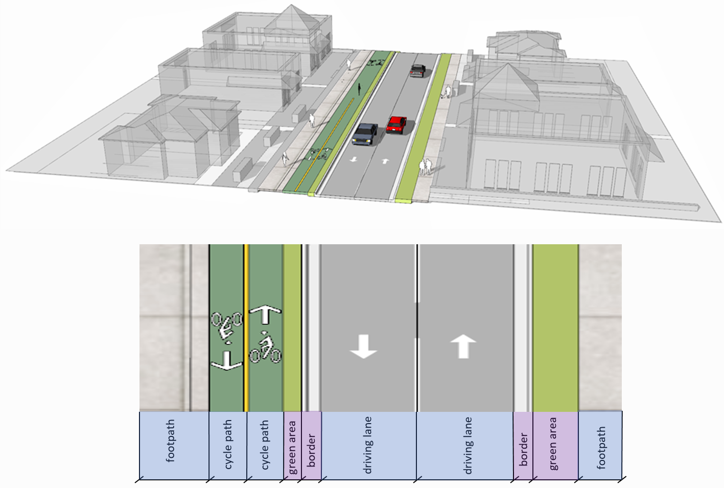
Figure 12 Section with one carriageway decomposed into individual TrafficAreas (blue) and AuxiliaryTrafficAreas (purple) (own illustration based on SketchUp model).
The median and grass areas in this example is modelled as AuxiliaryTrafficAreas with an attribute surface material = “grass”. In addition these areas can be modelled as Vegetation objects (PlantCover) linked to corresponding AuxiliaryTrafficAreas using a CityObjectRelation with the value “equal”. This approach can be helpful for accurately calculating (non-)sealed surfaces within a city.
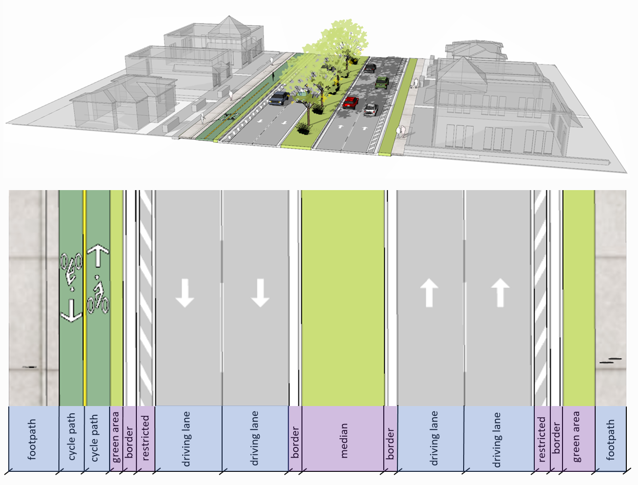
Figure 13 Section with two carriageways decomposed into individual TrafficAreas (blue) and AuxiliaryTrafficAreas (purple) (own illustration based on SketchUp model).
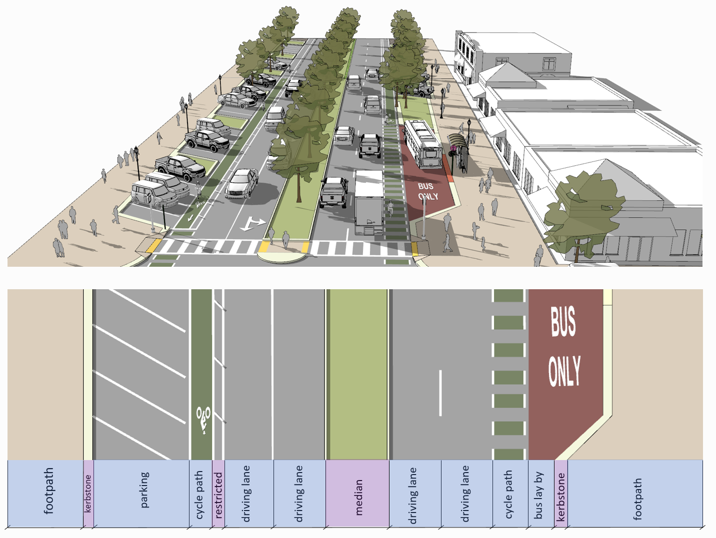
Figure 14 Section with two carriageways decomposed into individual TrafficAreas (blue) including parking and bus lanes and AuxiliaryTrafficAreas (purple) (own illustration based on SketchUp model).
While kerbstones normally are intended to separate driving lanes from pedestrian walking areas (and thus are considered AuxiliaryTrafficAreas) one could argue, that kerbstones can be used by pedestrians and thus should be modelled as TrafficAreas. Depending on intended applications, either categorization of kerbstones is possible.
3.5. Clearance Spaces
Definition
A ClearanceSpace represents the actual free space above a TrafficArea within which a mobile object can move without contacting an obstruction.
Each ClearanceSpace
must contain a unique gml:id attribute.
should be represented using volumetric geometries.
can contain a class attribute.
3.6. Markings
Markings are modelled as an individual class.
Definition
A Marking is a visible pattern on a transportation area relevant to the structuring or restriction of traffic. Examples are road markings and markings related to railway or waterway traffic.
Each Marking
must contain a unique gml:id attribute.
should contain a class attribute indicating its type.
should be represented as additional surfaces independent of level of granularity.
should be represented with individual objects for each Marking.
should be represented using polygonal geometries depicting the actual shape of each Marking.
can span over multiple (Auxiliary)TrafficAreas.
can be linked to a corresponding TrafficArea via a CityObjectRelation (e.g. to indicate the validity of a marking for a certain lane).
Individual lines part of a dashed line e.g. can also be aggregated.
Colored surfaces (e.g. a red or green bicycle path) should not be modelled as Markings but as corresponding TrafficAreas with a suitable color or texture.
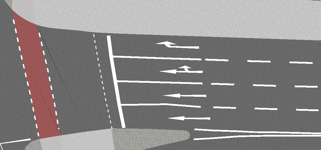
Figure 15 Different types of Markings including stop lines, dashed lines, arrows and zebra crossings.
citygml_class (text) |
citygml_class (code) |
|---|---|
road_marking |
11 |
road_marking_direction |
12 |
road_marking_lane |
13 |
road_marking_restricted |
14 |
road_marking_crosswalk |
15 |
road_marking_stop |
16 |
arrowRight |
121 |
arrowLeft |
122 |
arrowStraight |
123 |
arrowStraightRight |
124 |
arrowStraightLeft |
125 |
road_marking_lane_broken |
131 |
road_marking_lane_solid |
132 |
symbol_bicycle |
140 |
symbol_other |
150 |
3.7. Holes
Holes are modelled as an individudal class.
Definition
A Hole is an opening in the surface of a Road, Track or Square such as road damages, manholes or drains. Holes can span multiple transportation objects.
Each Hole
must contain a unique gml:id attribute.
can contain an class attribute indicating its type.
Definition
A HoleSurface is a representation of the ground surface of a hole.
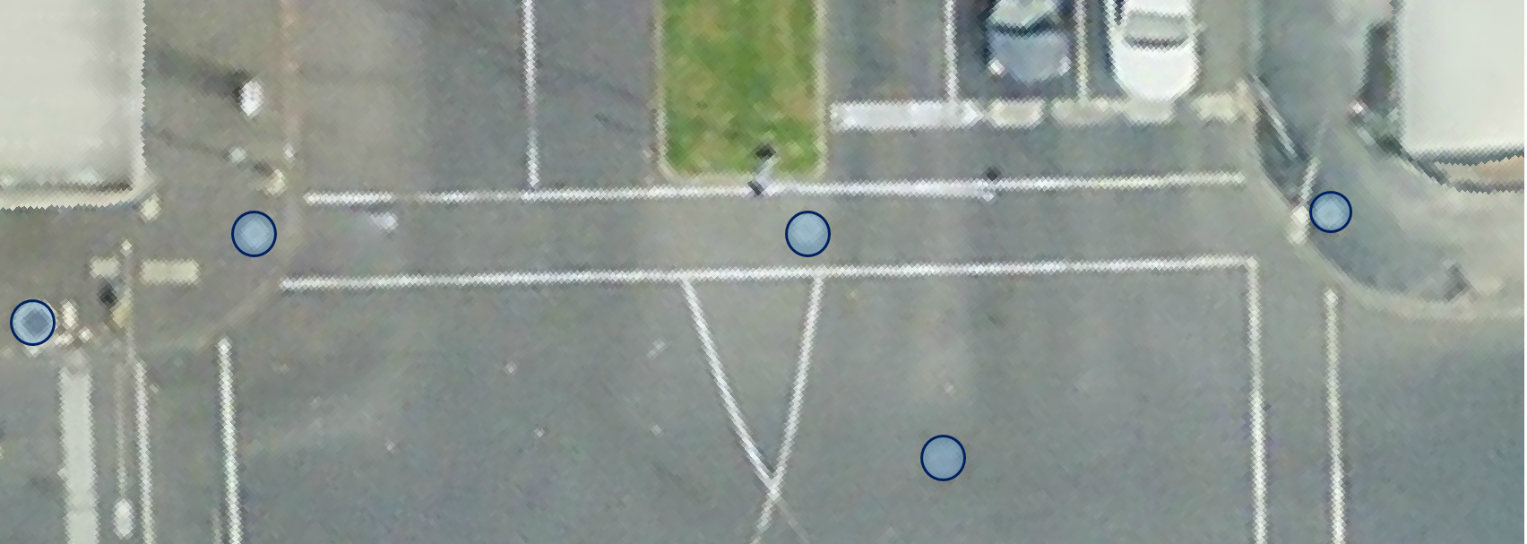
Figure 16 Manhole covers modelled as Holes.
3.8. Tracks
Definition
A Track is a small path mainly used by pedestrians.
Each Track
must contain a unique gml:id attribute.
should consist of individual Sections and Intersections.
can contain multiple function and usage attributes.
can contain a class attribute.
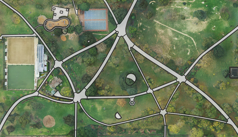
Figure 17 TrafficAreas part of Tracks within a park.
3.9. Squares
Definition
A Square is a transportation space for unrestricted movement of vehicles, bicycles and/or pedestrians. This includes plazas as well as large sealed surfaces such as parking lots or gas stations.
Each Square
must contain a unique gml:id attribute.
is not segmented into Sections and Intersections
should contain a function attribute indicating the type (e.g. parking lot or plaza).
can contain multiple function and usage attributes.
can be segmented into individual (Auxiliary)TrafficSpaces bounded by (Auxiliary)TrafficAreas. Individual parking slots within a bigger parking lot for example can be modelled as individual TrafficAreas.
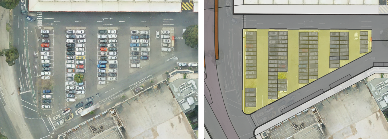
Figure 18 A parking lot segmented into individual TrafficAreas (parking slots and driving surfaces) modelled as a Square.
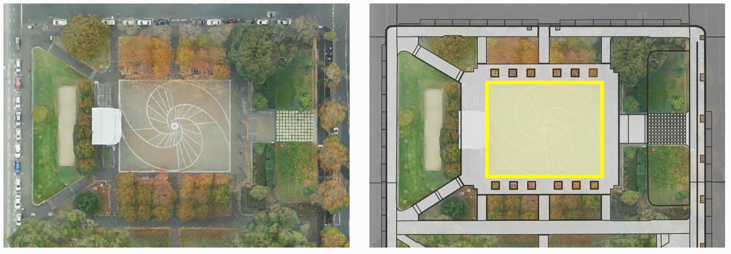
Figure 19 A plaza modelled as a Square surrounded by Tracks.
4. Modelling examples
The following examples are intended to illustrate modelling concepts of the CityGML 3.0 Transportation module. Most corresponding datasets are provided as open data.
First, examples of individual Sections and Intersections with corresponding (Auxiliary)TrafficSpaces and (Auxiliary)TrafficAreas are shown.
Then, it is shown how more complex scenarios can be segmented into Sections and Intersections as well.
4.1. Individual Section with one carriageway
This example dataset can be found here.
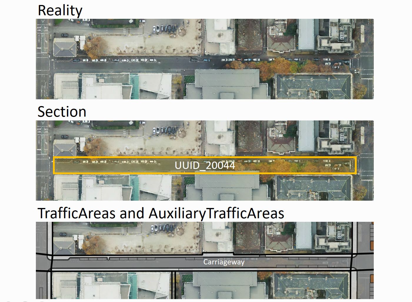
Figure 20 Individual Section with one carriageway.
<core:cityObjectMember>
   <tran:Road gml:id="UUID_Little_Lonsdale_Street">
      <gml:name>Little_Lonsdale_Street</gml:name>
      <tran:section>
         <tran:Section gml:id="UUID_20044">
            <tran:trafficSpace>
               <tran:TrafficSpace gml:id="UUID_TS_id_4c95049e-1b96-4a39-b678-29ce209cddb5">
                  <core:boundary>
                     <tran:TrafficArea gml:id="UUID_TA_0bd21839-0ced-4660-8c21-75dbf633ec7a">
                        <core:lod2MultiSurface>
                           <gml:MultiSurface srsName="EPSG:32755" srsDimension="3">
                              <!Geometry definition>
                           </gml:MultiSurface>
                        </core:lod2MultiSurface>
                        <tran:function>2</tran:function>
                        <tran:surfaceMaterial>3</tran:surfaceMaterial>
                        <!Additional attributes such as area in sqm, etc.>
                     </tran:TrafficArea>
                  </core:boundary>
                  <tran:granularity>way</tran:granularity>
               </tran:TrafficSpace>
            </tran:trafficSpace>
            <!Additional (Auxiliary)TrafficSpaces with corresponding (Auxiliary)TrafficAreas>
         </tran:Section>
      </tran:section>
   </tran:Road>
</core:cityObjectMember>
4.2. Individual Section with two carriageways
This example dataset can be found here.
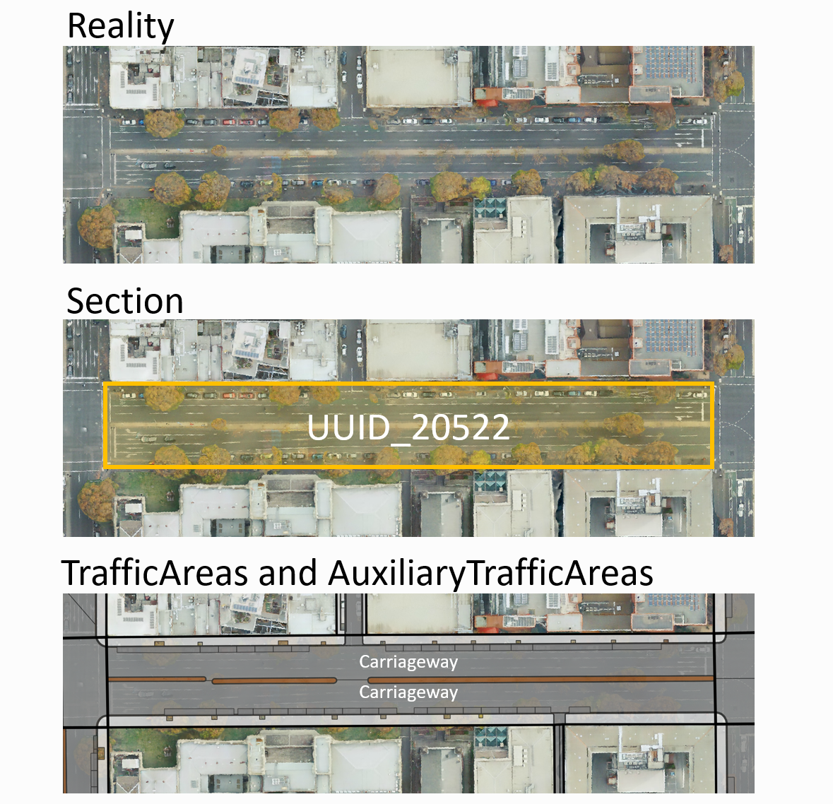
Figure 21 Individual Section with two carriageways.
<core:cityObjectMember>
   <tran:Road gml:id="UUID_Lygon_Street">
      <gml:name>Lygon_Street</gml:name>
      <tran:section>
         <tran:Section gml:id="UUID_20522">
            <tran:trafficSpace>
               <tran:TrafficSpace gml:id="UUID_TS_id_5c249b72-82c3-47ef-9be3-e3de6340c6cd">
                  <core:boundary>
                     <tran:TrafficArea gml:id="UUID_TA_72cc6ac7-caf4-439b-b08a-707c5dd3f506">
                        <core:lod2MultiSurface>
                           <gml:MultiSurface srsName="EPSG:32755" srsDimension="3">
                              <!Geometry definition>
                           </gml:MultiSurface>
                        </core:lod2MultiSurface>
                        <tran:function>2</tran:function>
                        <tran:surfaceMaterial>3</tran:surfaceMaterial>
                        <!Additional attributes such as area in sqm, surface material, etc.>
                     </tran:TrafficArea>
                  </core:boundary>
                  <tran:granularity>way</tran:granularity>
               </tran:TrafficSpace>
            </tran:trafficSpace>
            <tran:trafficSpace>
               <tran:TrafficSpace gml:id="UUID_TS_id_cdbf9131-027f-425f-a355-f605d04a4f84">
                  <core:boundary>
                     <tran:TrafficArea gml:id="UUID_TA_ae280a29-8d9a-49c0-bf74-ffea469290d6">
                        <core:lod2MultiSurface>
                           <gml:MultiSurface srsName="EPSG:32755" srsDimension="3">
                              <!Geometry definition>
                           </gml:MultiSurface>
                        </core:lod2MultiSurface>
                        <tran:function>2</tran:function>
                        <tran:surfaceMaterial>3</tran:surfaceMaterial>
                        <!Additional attributes such as area in sqm, etc.>
                     </tran:TrafficArea>
                  </core:boundary>
                  <tran:granularity>way</tran:granularity>
               </tran:TrafficSpace>
            </tran:trafficSpace>
            <!Additional (Auxiliary)TrafficSpaces with corresponding (Auxiliary)TrafficAreas>
         </tran:Section>
      </tran:section>
   </tran:Road>
</core:cityObjectMember>
4.3. Three-way Intersection
This example dataset can be found here.
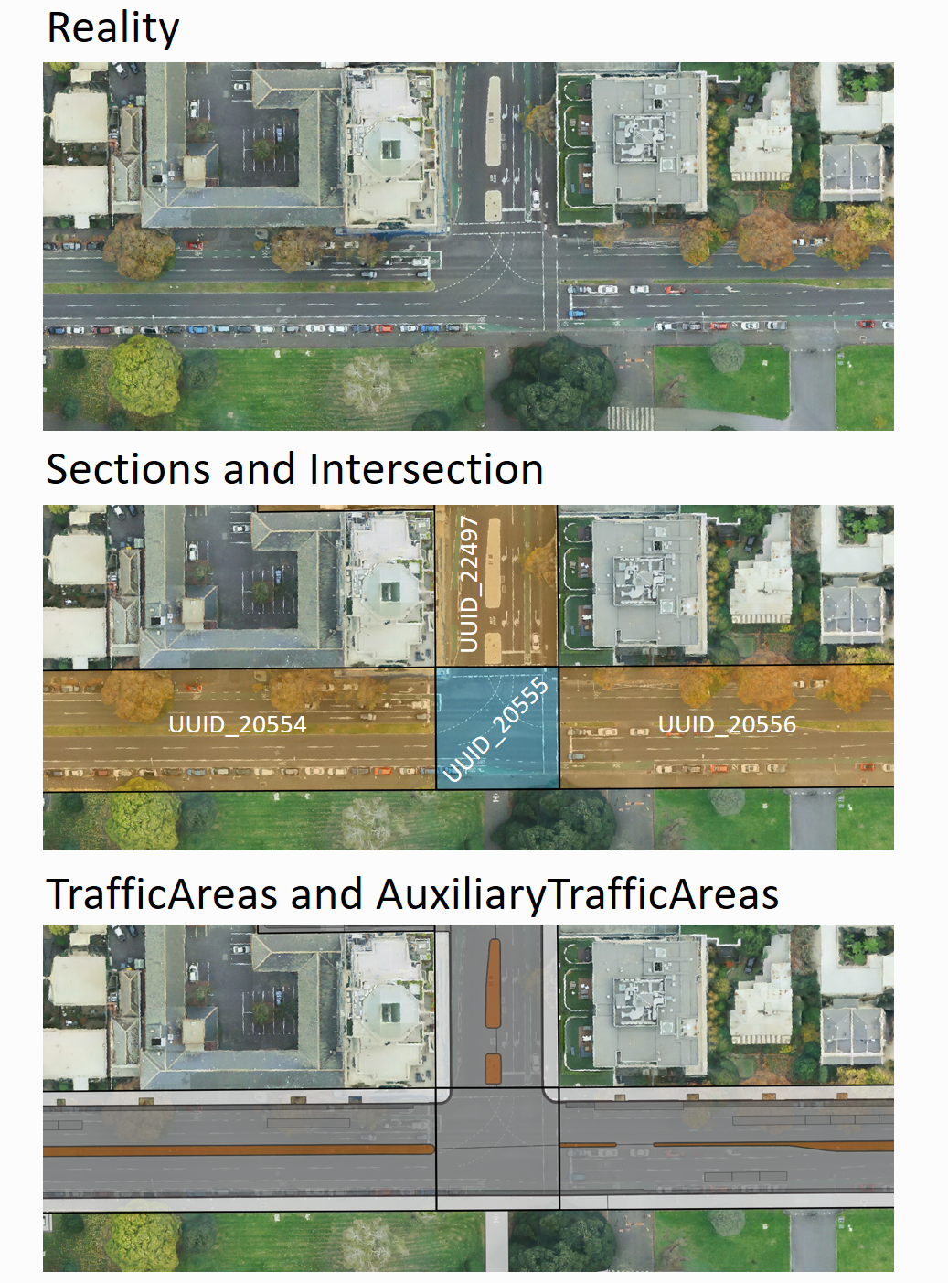
Figure 22 Intersection with three adjacent Sections.
<core:cityObjectMember>
   <tran:Road gml:id="UUID_Queensberry_Street">
      <gml:name>Queensberry_Street</gml:name>
      <tran:section>
         <tran:Section gml:id="UUID_22497">
            <!(Auxiliary)TrafficSpaces with corresponding (Auxiliary)TrafficAreas>
         </tran:Section>
      </tran:section>
      <tran:intersection xlink:href="#UUID_20555"/>
   </tran:Road>
</core:cityObjectMember>
<core:cityObjectMember>
   <tran:Road gml:id="UUID_Rathdowne_Street">
      <gml:name>Rathdowne_Street</gml:name>
      <tran:section>
         <tran:Section gml:id="UUID_20554">
            <!(Auxiliary)TrafficSpaces with corresponding (Auxiliary)TrafficAreas>
         </tran:Section>
      </tran:section>
      <tran:section>
         <tran:Section gml:id="UUID_20556">
            <!(Auxiliary)TrafficSpaces with corresponding (Auxiliary)TrafficAreas>
         </tran:Section>
      </tran:section>
      <tran:intersection>
         <tran:Intersection gml:id="UUID_20555">
         <gml:name>Queensberry_Street</gml:name>
         <gml:name>Rathdowne_Street</gml:name>
            <!(Auxiliary)TrafficSpaces with corresponding (Auxiliary)TrafficAreas>
         </tran:Intersection>
      </tran:intersection>
   </tran:Road>
</core:cityObjectMember>
4.4. Four-way Intersection
This example dataset can be found here.
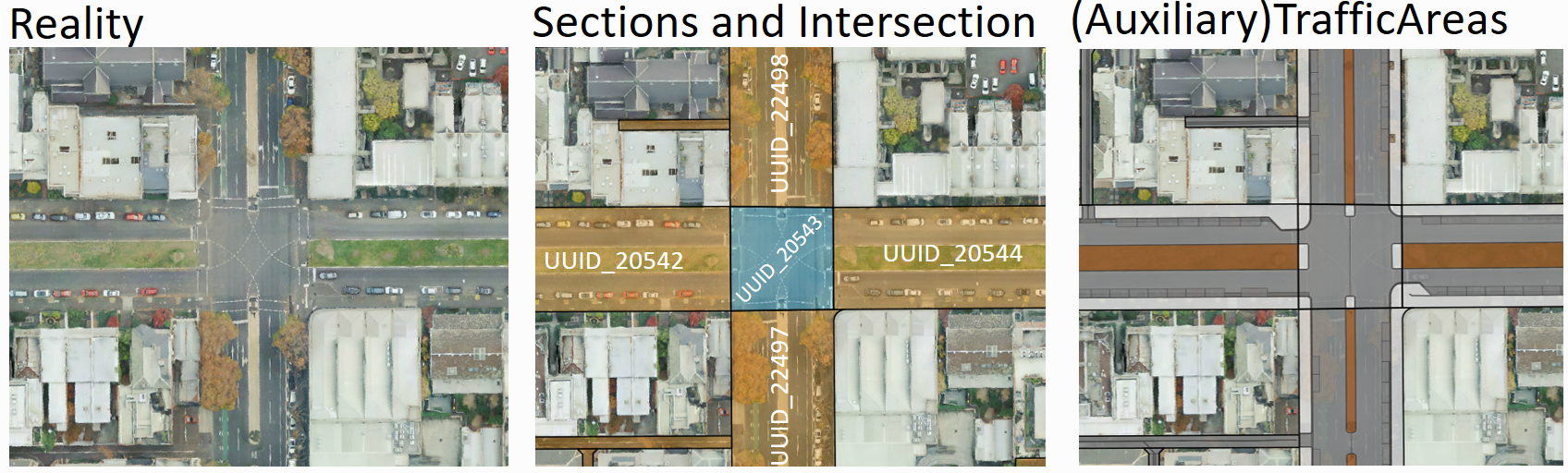
Figure 23 Intersection with four adjacent Sections.
<core:cityObjectMember>
   <tran:Road gml:id="UUID_Queensberry_Street">
      <gml:name>Queensberry_Street</gml:name>
      <tran:section>
         <tran:Section gml:id="UUID_22497">
            <!(Auxiliary)TrafficSpaces with corresponding (Auxiliary)TrafficAreas>
         </tran:Section>
      </tran:section>
      <tran:section>
         <tran:Section gml:id="UUID_22498">
            <!(Auxiliary)TrafficSpaces with corresponding (Auxiliary)TrafficAreas>
         </tran:Section>
      </tran:section>
      <tran:intersection xlink:href="#UUID_20543"/>
   </tran:Road>
</core:cityObjectMember>
<core:cityObjectMember>
   <tran:Road gml:id="UUID_Drummond_Street">
      <gml:name>Drummond_Street</gml:name>
      <tran:section>
         <tran:Section gml:id="UUID_20544">
            <!(Auxiliary)TrafficSpaces with corresponding (Auxiliary)TrafficAreas>
         </tran:Section>
      </tran:section>
      <tran:section>
         <tran:Section gml:id="UUID_20542">
            <!(Auxiliary)TrafficSpaces with corresponding (Auxiliary)TrafficAreas>
         </tran:Section>
      </tran:section>
      <tran:intersection>
         <tran:Intersection gml:id="UUID_20543">
         <gml:name>Queensberry_Street</gml:name>
         <gml:name>Drummond_Street</gml:name>
            <!(Auxiliary)TrafficSpaces with corresponding (Auxiliary)TrafficAreas>
         </tran:Intersection>
      </tran:intersection>
   </tran:Road>
</core:cityObjectMember>
4.5. Small roundabout
This example dataset can be found here.
Small roundabouts can be modelled as an Intersection.
The structure of the corresponding CityGML (XML) document is the same as in XML example 4.
The specific type of Intersection (in this case ‘roundabout’) can be indicated with a corresponding class attribute.
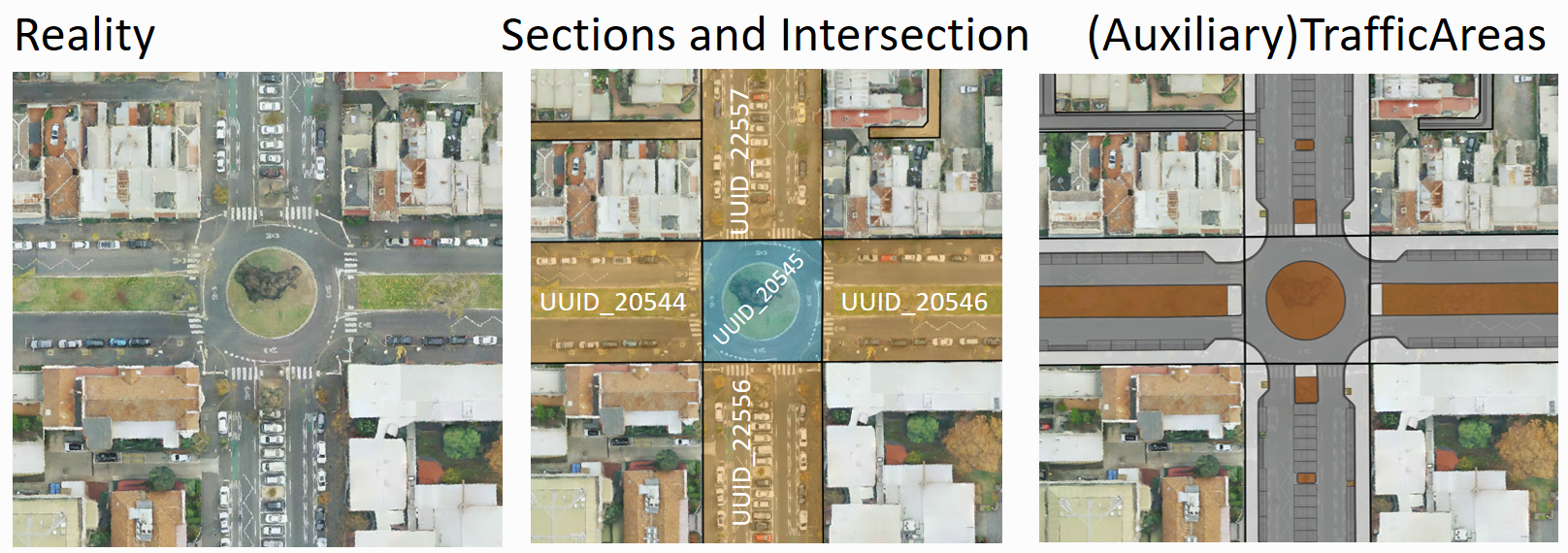
Figure 24 Small Roundabout modelled as Intersection with four adjacent Sections.
4.6. Large roundabout
While it is possible to model a large roundabout as a single Intersection it might be beneficial to divide large roundabouts into multiple Sections and Intersections.
Figure 25 shows an example of a large roundabout segmented into multiple Sections (orange) and Intersection (blue) with corresponding (Auxiliary)TrafficAreas in granularity ‘way’.
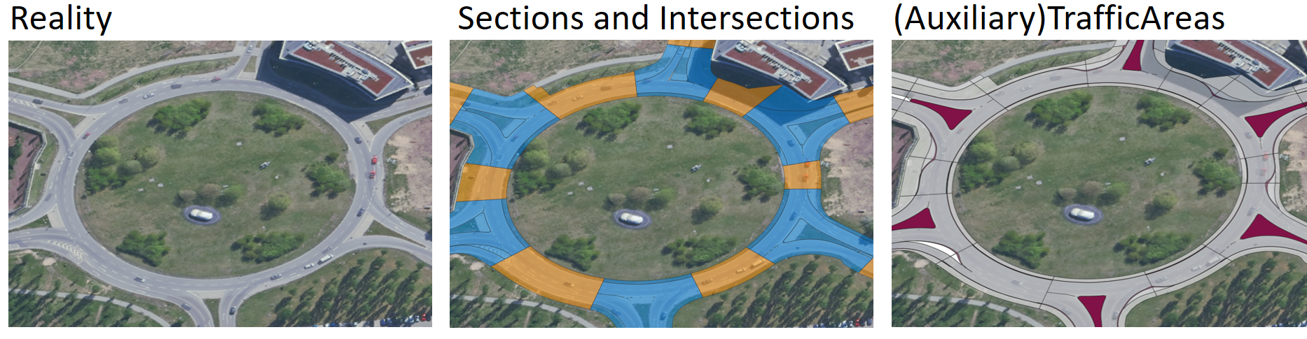
Figure 25 A large roundabout segmented into multiple Sections (orange) and Intersections (blue).
4.7. Small side streets
Sections and Intersection do not need to alternate.
In some cases it might be useful to have several Sections directly next to each other.
Especially small side streets can be modelled as individual Sections, that can be directly adjacent to Sections of larger Roads.
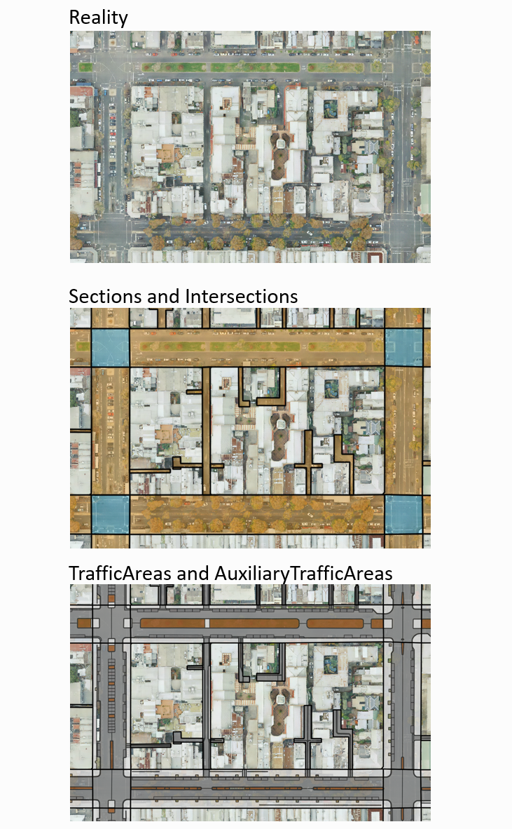
Figure 26 Small side street modelled as individual Sections directly connected to larger Sections.
4.8. Dead end
Dead ends should be modelled as independent Sections
While dead ends can be connected to another Section directly, it is recommended to connect dead ends with an Intersection as depicted in figure Figure 27.
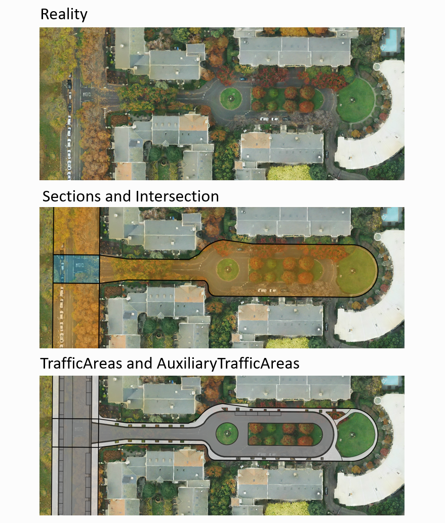
Figure 27 Dead end modelled as individual Section.
4.9. Complex motorway interchange
The following example shows a complex motorway derived from OpenDRIVE data using the open-source tool r:trån.
Motorway entries and exits should be modelled as individual Sections.
The interchange is segmented into smaller Sections and Intersections each further divided into TrafficAreas and AuxiliaryTrafficAreas.
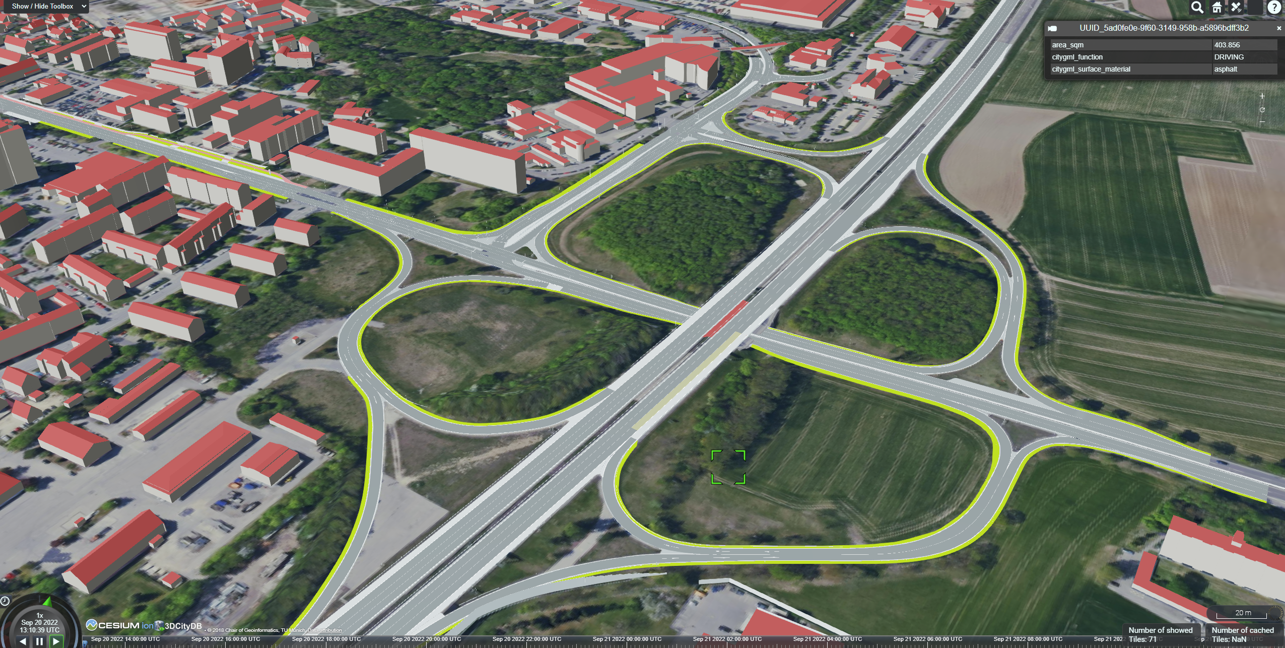
Figure 28 Motorway interchange available in CityGML 3.0 derived from OpenDRIVE data using the open-source converter r:trån.
5. Integrated representation of multiple transportation types
5.1. Roads and Railways
Definition
A Railway is a transportation space used by wheeled vehicles on rails. This can include trains or trams.
Roads and Railways often do not just coexist next to each other but sometimes directly interact and share identical spaces and surfaces.
The Section / Intersection concept applies to Roads as well as Railways.
This allows an integrated (and non-redundant) modelling of both transportation types.
5.1.1. Railway level crossing
Level crossing shared by Roads and Railways can be modelled as an Intersection.
This Intersection then can be linked to both FeatureTypes using XLinks.
TrafficAreas within an Intersection that is part of a Road as well as a Railway object, should contain multiple function attributes (e.g. ‘driving lane’ as well as ‘railway lane’).
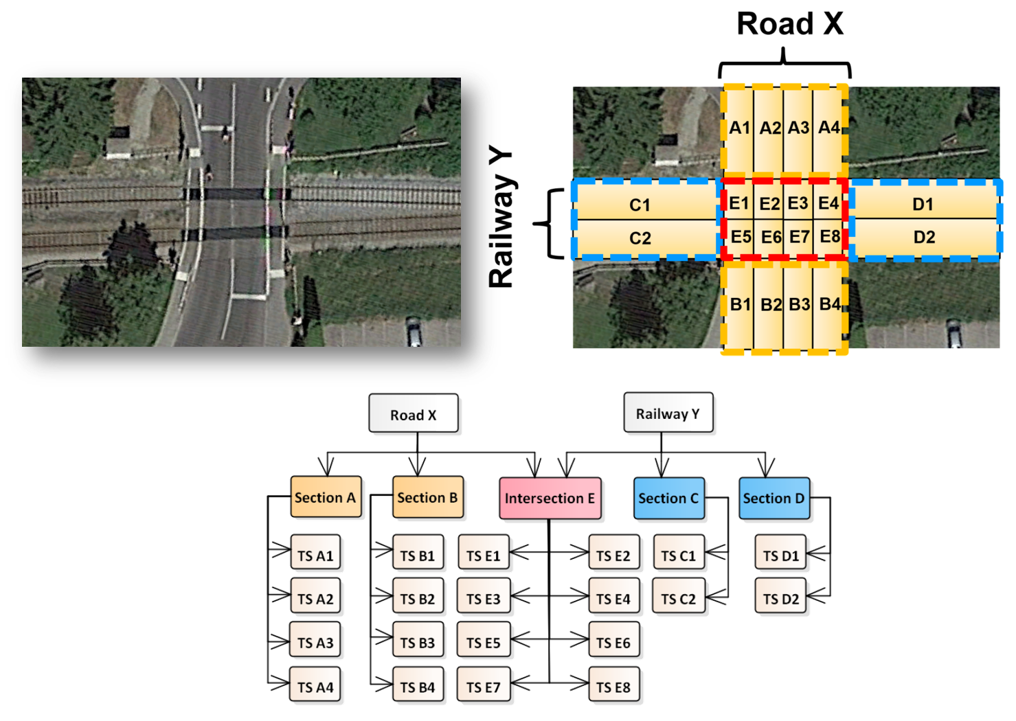
Figure 29 Level crossing of a Road and a Railway object sharing an Intersection.
5.1.2. Tramway within a Road
Tramways within a Road can be modelled as TrafficAreas with multiple function attributes (e.g. railway and driving lane).
These TrafficAreas can be linked to multiple Intersections.
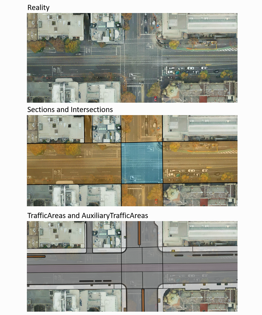
Figure 30 A tramway within a Road. Surfaces of the tramway are TrafficAreas with multiple functions linked to respective Intersections.
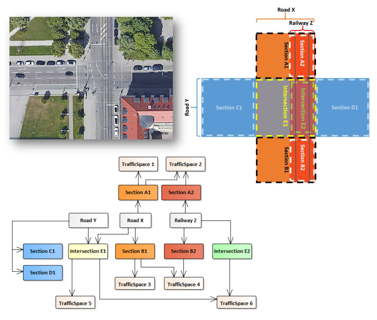
Figure 31 Object diagram of a tramway surface part of multiple Intersections.
5.2. Roads on Bridges
Road surfaces on a Bridge can be modelled as TrafficAreas (as part of a Road) and RoofSurfaces (as part of a Bridge) at the same time.
In the example shown in Figure 32, TrafficArea 6 and RoofSurface 2 represent the same (geometric) surface but are part of different (semantic) objects.
Using CityObjectRelations in order to express this relation is shown in XML example 5.
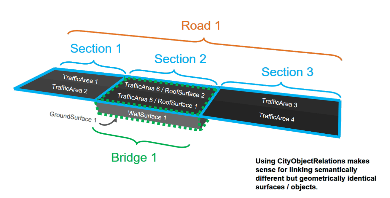
Figure 32 Shared surfaces by Roads and Bridges using CityObjectRelations
An example dataset can be downloaded here.
<tran:TrafficArea gml:id="id_trafficarea6">
   <core:relatedTo>
      <core:CityObjectRelation>
         <core:relationType>equal</core:relationType>
            <core:relatedTo xlink:href="id_roofSurface2"/>
         </core:CityObjectRelation>
      </core:relatedTo>
      <core:lod2MultiSurface>
         <!Geometry definition>
      </core:lod2MultiSurface>
</tran:TrafficArea>
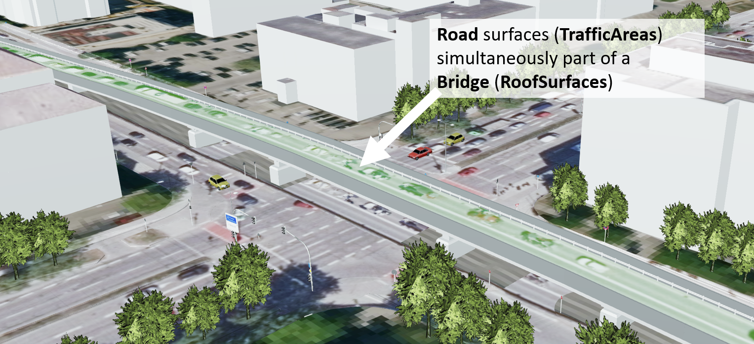
Figure 33 TrafficAreas part of a Road are simultaneously modelled as RoofSurfaces part of a Bridge.
5.3. Roads through Tunnels
Roads can run trough Tunnel objects.
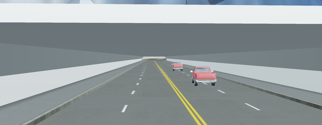
Figure 34 Roads within a 3D model of a Tunnel.
5.4. Roads within Buildings (Parking garage)
Transportation networks and Roads can reach into Buildings (e.g. within a parking garage).
In this case, TrafficAreas are also Floor- or RoofSurfaces.
An example dataset can be downloaded here.
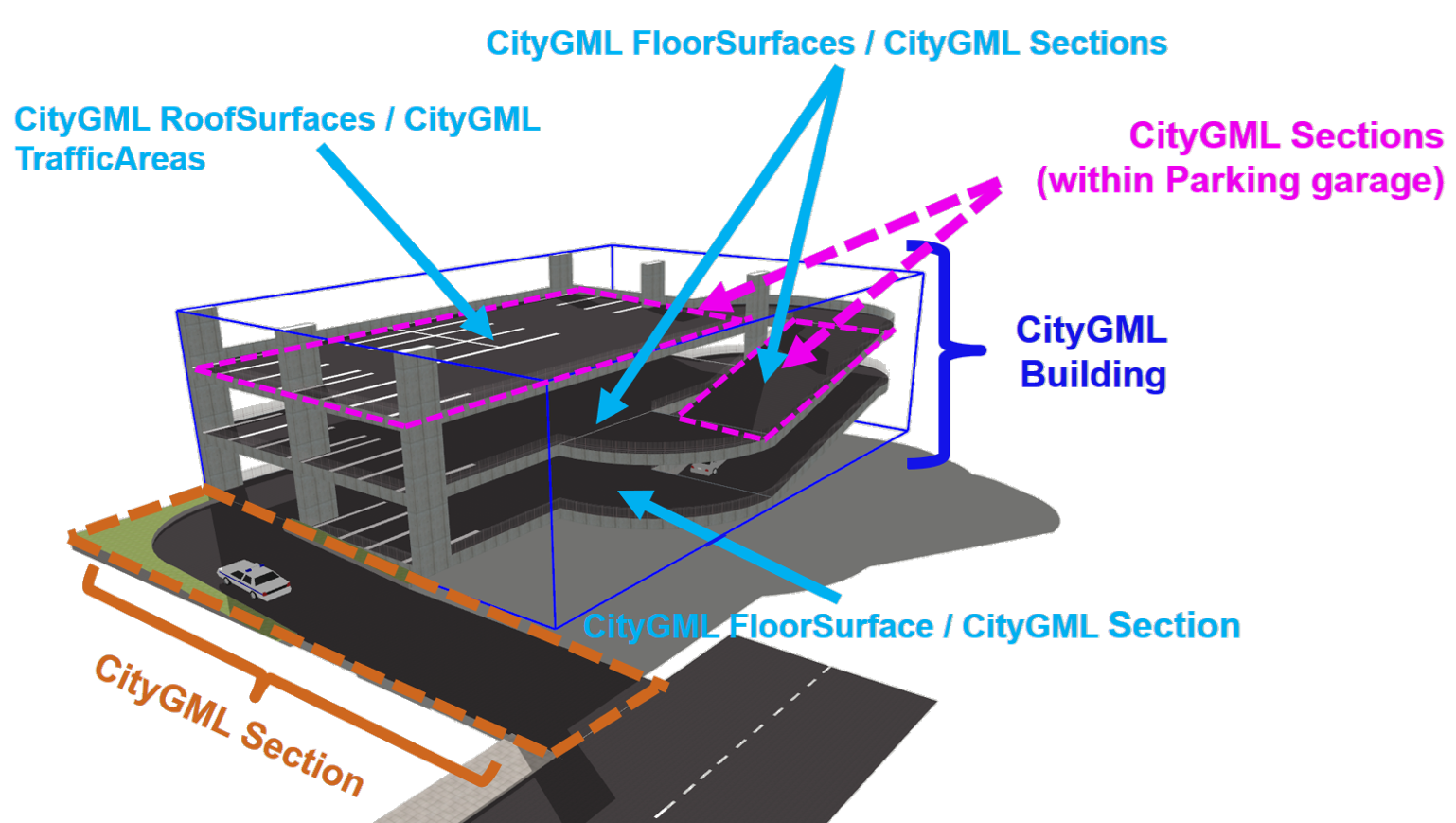
Figure 35 Individual CityFurniture objects with different functions part of a CityObjectGroup.
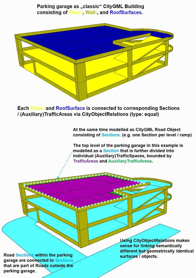
Figure 36 Modelling shared surfaces by Buildings and Roads (e.g. within a parking garage) using CityObjectRelations.
5.5. Roads and Waterways
The same concept of shared Intersections of Roads and Railways also applies for Roads and Waterways.
This can be useful to model ford crossings.
6. Other relevant CityGML modules
In addition to Roads, other thematic parts of semantic 3D city models can be relevant for certain streetspace applications. This includes objects such as roadside Vegetation or CityFurniture (including traffic signs and lights).
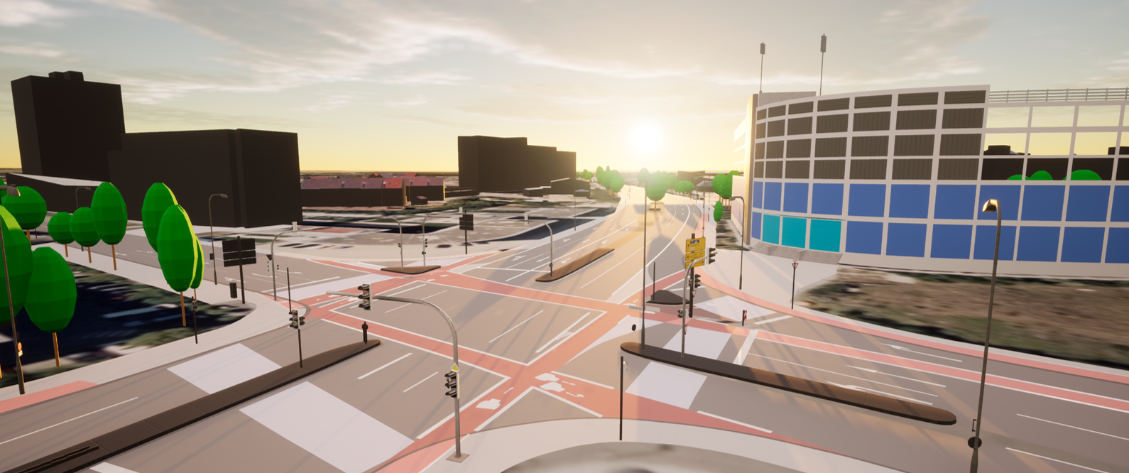
Figure 37 Components of a semantic 3D city model relevant for streetspace applications (CityGML model visualized in the Unreal Engine).
6.1. CityFurniture
Concepts for modelling city furniture are provided within a specific CityFurniture module.
Definition
CityFurniture is an object or piece of equipment installed in the outdoor environment for various purposes. Examples include street signs, traffic signals, street lamps, benches, trash bins, bike racks or fountains.
Each CityFurniture object
must contain a unique gml:id attribute.
should be modelled per single object.
should contain a function attribute according to the CityGML codelist.
should contain a class attribute (e.g. to indicate sign, light or pole type)
should contain relevant information such as 2D coordinates, height information (absolute or above the ground) and orientation (e.g. azimuth angle).
can use CityObjectRelations to indicate validity of a certain traffic sign or light for a specific lane.
These objects are usually represented with prototypes, which are instantiated multiple times at different locations (implicit geometries). However, it is also possible to model these objects using a simple point representation.
Multiple logically connected objects (such as all signs and traffic lights connected to one pole) can be part of a CityObjectGroup.
Many countries use standardized codes to identify different types of traffic signs (e.g. Germany). It is recommended to use these codes as class attributes with each traffic sign object.
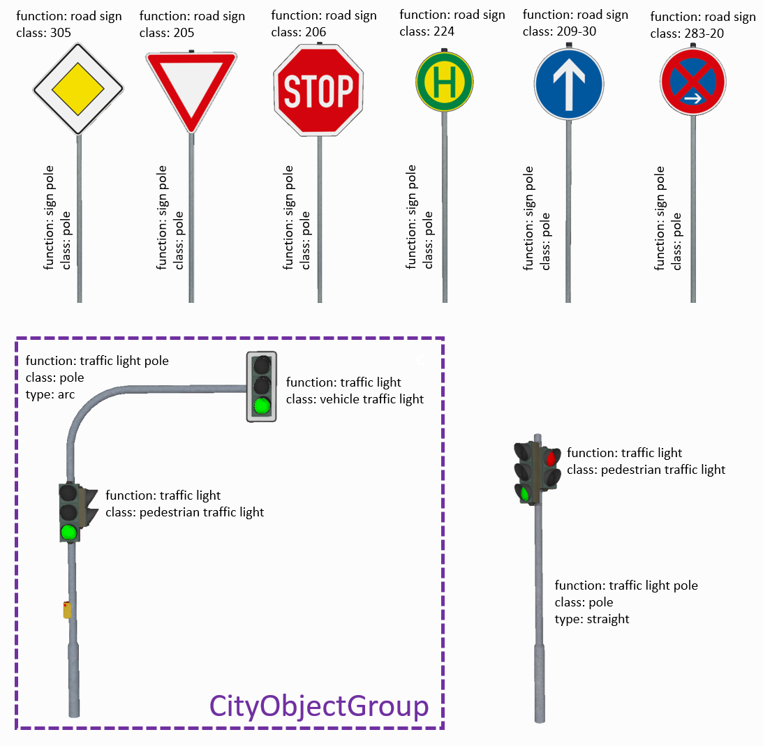
Figure 38 Traffic signs (top) and traffic lights (bottom) and corresponding poles modelled as individual CityFurniture objects.
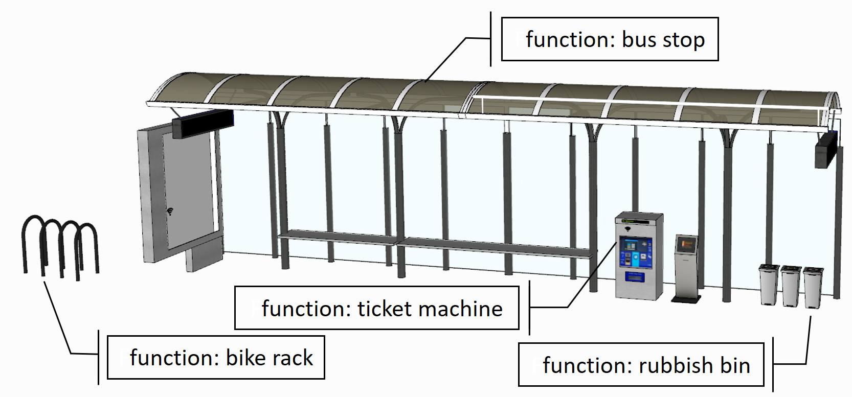
Figure 39 Bus stop and other city furniture objects with corresponding function attributes.
6.2. Vegetation
Concepts for modelling vegetation are provided within a specific Vegetation module.
Similar to CityFurniture, these objects are usually represented with prototypes using implicit geometries.
Vegetation can be represented either as SolitaryVegetationObjects, such as trees, bushes and ferns, or as vegetation areas (PlantCovers) of a given species or a typical mixture of plant species, such as forests, steppes and wet meadows.
PlantCovers can be equal to AuxiliaryTrafficAreas (e.g. green areas or medians within a Road). This relation can be expressed using CityObjectRelations. This approach can be helpful for accurately calculating (non-)sealed surfaces within a city.
Vegetation models can be abstract representations derived from height, trunk diameter and crown diameter information or more realistic 3D models.
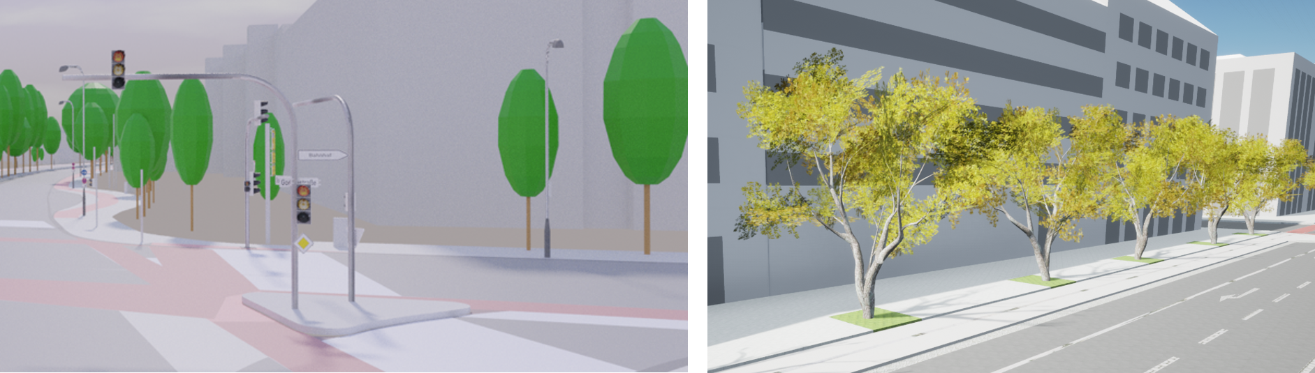
Figure 40 Vegetation objects such as trees represented using abstract (left) and more detailed (right) 3D models.
6.3. Bridge
Concepts for modelling bridges are provided within a specific Bridge module.
Definition
Bridges are defined as a structure that affords the passage of pedestrians, animals, vehicles, and service(s) above obstacles or between two points at a height above ground.
6.4. Tunnel
Concepts for modelling tunnels are provided within a specific Tunnel module.
Definition
Tunnels are defined as a horizontal or sloping enclosed passage way of a certain length, mainly underground or underwater.
6.5. Dynamizer
The Dynamizer module provides the concepts that enable representation of time-varying data for city object properties as well as for integrating sensors with 3D city models.
In the context of street space modelling, this can be used for linking driving lanes with dynamic information on induction loops or for representing traffic light signals.
This article by Chaturvedi & Kolbe explains concepts for integration dynamic information (such as sensors) with semantic 3D city models.
Definition
Dynamizers are objects that inject time series data for an individual attribute of the city object in which the Dynamizer is included. In order to represent dynamic (time-dependent) variations of its value, the time series data overrides the static value of the referenced city object attribute.
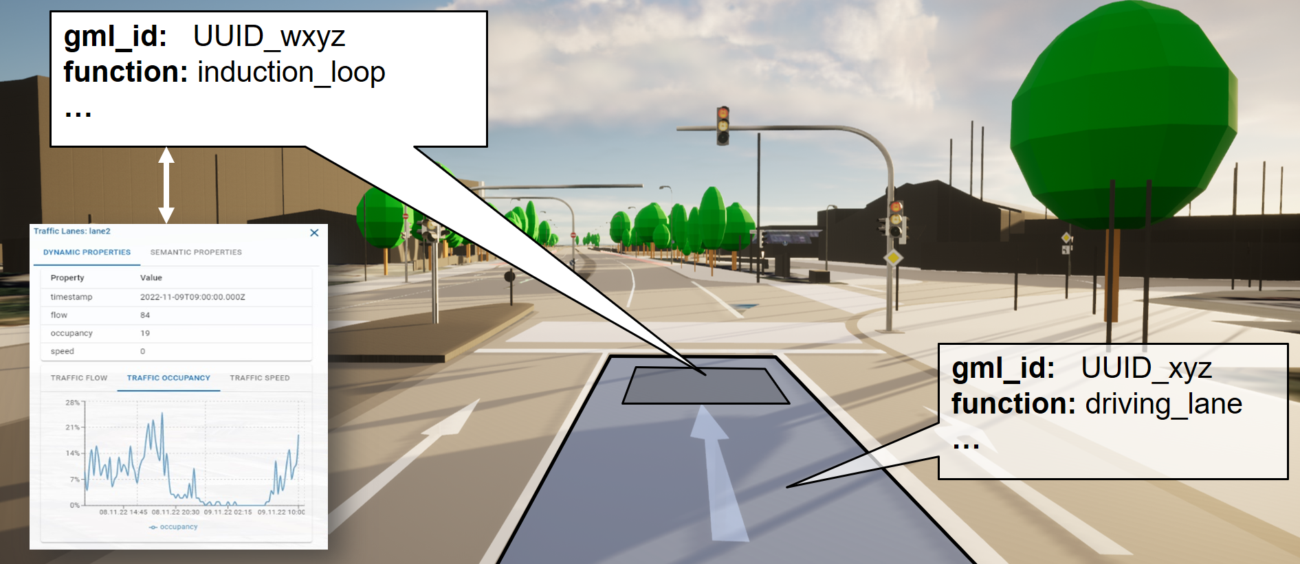
Figure 41 Induction loop within a driving lane linked with time-varying traffic occupancy data.
7. Interactive online demos
Hint
A collection of interactive visualizations of streetspace models for cities including New York City, Melbourne, Munich, and Tokyo can be found here.
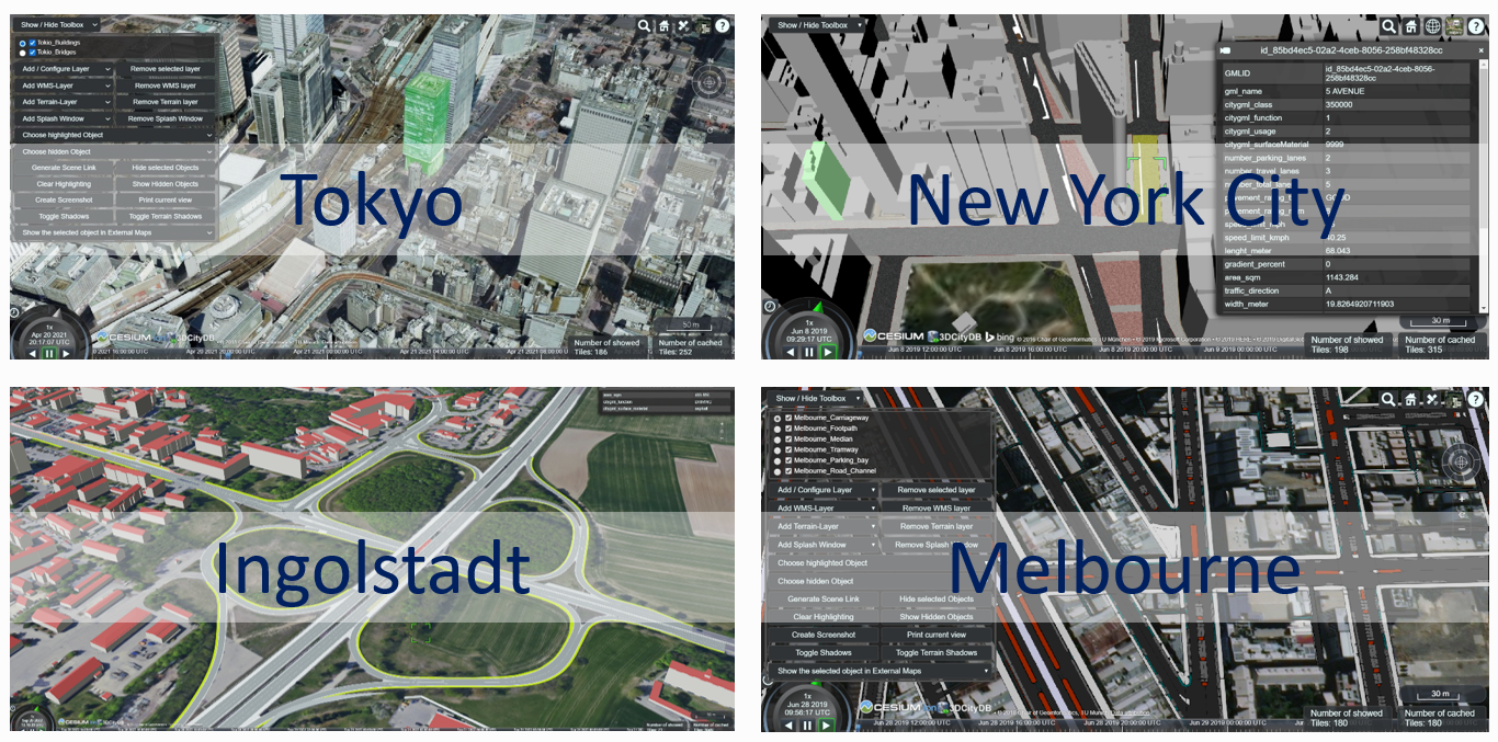
Figure 42 Impressions of interactive web-based visualizations of streetspace models for different cities.